25+ direct conversion receiver block diagram
P02 is a GPIO digital pin. Each polyphase filter ρ k n operating at the original sampling rate f s assuming 8 kHz is a downsampled version of the interpolation filter hn operating at the upsampling rate Lf s 32 kHz assuming an interpolation factor of L 4.
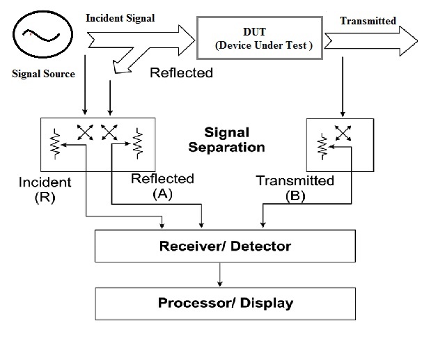
Network Analyzer Block Diagram Types Working Its Applications
The mixer is the popular NE602 SA612 IC.
. The range of the The range of the transmitter can be increased up to 5 me ter by using convex lens. These pins are power supply voltage for the IO ports as. - Factory calibrated to 1 typical - Software selectable frequencies range of 31 kHz to 32 MHz 31 kHz Low-Power Internal.
Using JCR 10kHz-225MHz VFO. Architectures Protocols and Applications. They are widely used in many electronic devices ranging from simplest clock generators to digital instruments like.
SCL0 is an I2C0 clock IO and open-drain op. 12 Block diagram The following figure shows a top-level block diagram of the MPC5777C. This strategy is called direct sampling or direct RF and it requires an extremely expensive ADC chip.
Oscillators convert direct current DC from a power supply to an alternating current AC signal. And T 2 is the absolute temperature of the heat sink R or K. This is information on a product in full production.
CAP00 is a capture ip for Timer-0 channel-0. The Internet of Things IoT is defined as a paradigm in which objects equipped with sensors actuators and processors communicate with each other to serve a meaningful purpose. Channel bandwidths from less than 200 kHz to 56 MHz are supported.
The AD9361 receiver LO operates from 70 MHz to 60 GHz and the transmitter LO operates from 47 MHz to 60 GHz range covering most licensed and unlicensed bands. In this paper we survey state-of-the-art methods protocols and applications in this new emerging area. PIC16F873 AND PIC16F876 BLOCK DIAGRAM FLASH Program Memory 13 Data Bus 8 14 Program Bus Instruction reg Program Counter 8 Level Stack 13.
Internet of Things. Of DAC Channels Resolution Max DAC Rate GSPS Max Tx Channel Bandwidth GHz No. COMPUTATIONAL SHELL e200z7 dual issue SWT STM INTC FPU VLE 16K I-Cache 16K D-Cache MMU e200z7 checker core complex DEBUG JTAG MMU.
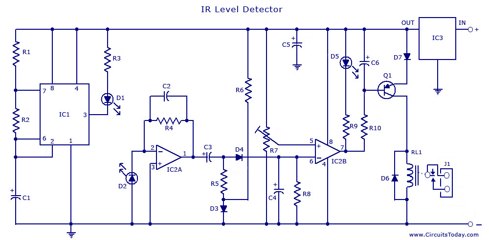
T 1 is the absolute temperature of the heat source R or K. Infrared IR remote controller comprises the tr ansmitter and receiver sections. Next we explain the properties of polyphase filters ie they have all-pass gain and possible different phases.
From Equation 71 there are three ways to increase ideal cycle efficiency. An electronic oscillator is an electronic circuit that produces a periodic oscillating electronic signal often a sine wave or a square wave or a triangle wave. EINT0 is an external interrupt 0-input.
The 28-pin and 40-pin pinouts are listed in Table 1-1 and Table 1-2 respectively. A stable yet inexpensive local oscillator was not available until Lee de Forest invented the triode. A third architecture one that is popular because its how old radios worked is known as superheterodyne.
In 1901 Reginald Fessenden demonstrated a direct-conversion heterodyne receiver or beat receiver as a method of making continuous wave radiotelegraphy signals audible. Direct Indirect and Relative Addressing modes. The two independent direct conversion receivers have state-of-the-art noise figure and linearity.
The purpose of the block diagram is to show the general interconnection of functional modules through the crossbar switch. - Two full 16-bit File Select Registers FSRs - FSRs can read program and data memory Flexible Oscillator Structure Precision 32 MHz Internal Oscillator Block. PWM3 is a pulse width modulator op-3.
The following device block diagrams are sorted by pin number. Pin 23 43 and 51- VDD. Pin22- P02 CAP00 SCL0.
January 2022 DS12991 Rev 4 194 STM32G030x6x8 Arm Cortex-M0 32-bit MCU up to 64 KB Flash 8 KB RAM 2x USART timers ADC comm. Device ID Register Values. Another option is to not downconvert at all and sample so fast to capture everything from 0 Hz to 12 the sample rate.
November 2021 DS9773 Rev 5 193 STM32F030x4 STM32F030x6 STM32F030x8 STM32F030xC Value-line Arm -based 32-bit MCU with up to 256 KB Flash timers ADC communication interfaces 24-36 V operation. Where η is thermal efficiency of conversion from heat into work. Fessendens receiver did not see much application because of its local oscillators stability problem.
For anyone interested in making a double conversion receiver with the SI5351 and SI473532 this is the block diagram of the receiver blocks that I built and it works great. This is information on a product in full production. 28-pin for Figure 1-1 and 40-pin for Figure 1-2.
RXD0 is a receiver ip for UART0. Decrease T 2 increase T 1 or bothLittle can be done to reduce T 2 in the Rankine cycle because of the limitations. Special Digital Features.
2
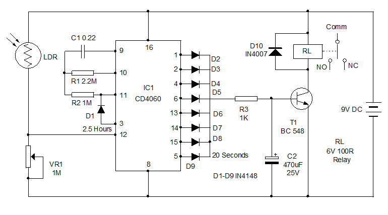
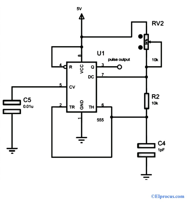
Infrared Ir Sensor Circuit Detector Circuit Diagram Using 555 Ic
2

Fuzzy Logic Enhanced Control For A Single Stage Grid Tied Photovoltaic System With Shunt Active Filtering Capability Ayachi Amor 2021 International Transactions On Electrical Energy Systems Wiley Online Library

K4icy S Home Brew Cw Audio Filter
How Many Microseconds Does It Take To Execute A 1 Cycle Instruction In Microchip Technology S Pic18 Quora
Types Of Timer Circuits With Schematics And Its Working Principle
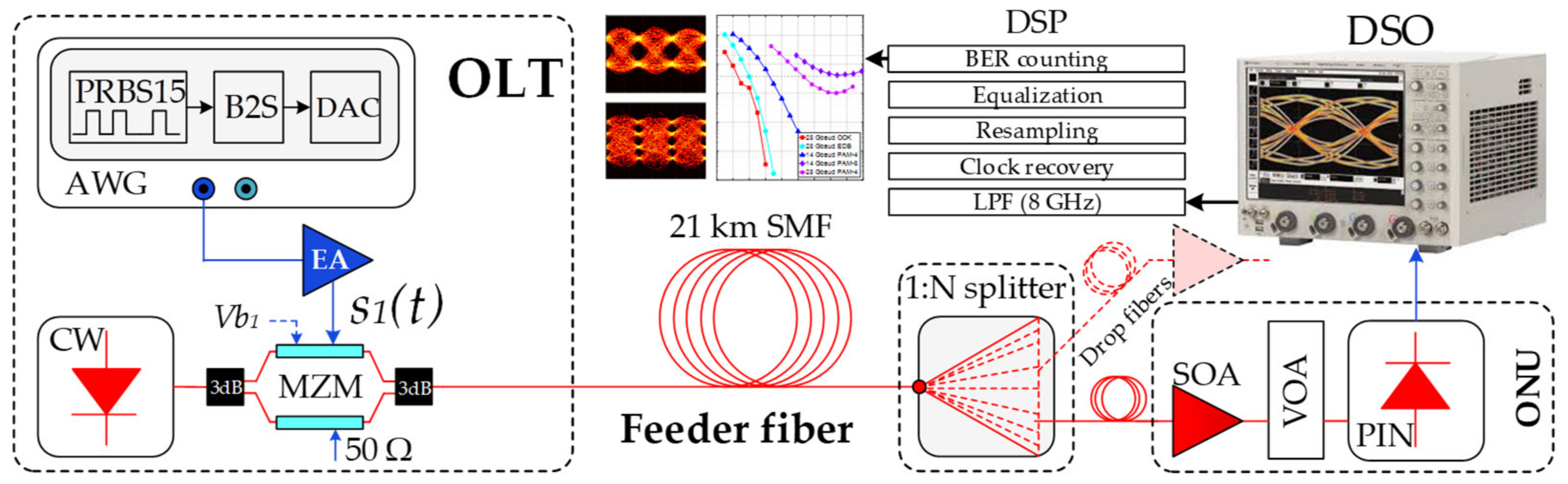
Applied Sciences Free Full Text Optical Power Budget Of 25 Gbps Im Dd Pon With Digital Signal Post Equalization Html

Transmitter Receiver An Overview Sciencedirect Topics
Frequency Counter Block Diagram Circuit Types And Its Applications
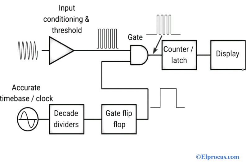
Frequency Counter Block Diagram Circuit Types And Its Applications
![]()
1khz Ir Transmitter Circuit
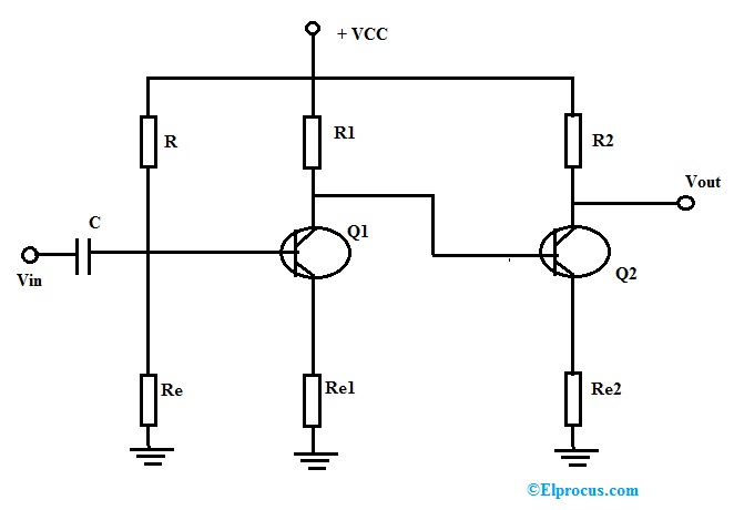
Dc Amplifier Working Characteristics Advantages Applications
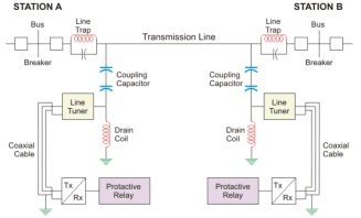
Power Line Carrier Communication Circuit Diagram And Its Working
2
Fet Questions Page 4 Uk Vintage Radio Repair And Restoration Discussion Forum
2